2. New technologies for textile functionalization
2.2. Electrospinning technology
Electrospinning is a method based on the use of electrostatic forces for producing continuous fibres with the diameter from between ten nanometres to a few micrometres. Such fine fibres cannot be produced with conventional methods for the production of nonwovens. The nanofibres formed with electrospinning have an exceptionally large active surface area per mass unit (fibre surface at diameter of 100 nm equals 40 m2 /g) and the spinning process itself enables a planned formation of the web structure (e.g. planned size of pores in the web by adjusting the nanofibre diameter and fibre thickness). Nanofibres can be electrospun from synthetic or natural polymers and their blends, from polymers with various nanoparticles (metal or ceramic), active substances etc. Also, individual fibres can be fabricated, as well as webs with a random or planned fibre arrangement. Fibres with a complex structure, e.g. core shell or hollow fi bres, can be produced with a special electrospinning method. Regarding the advantages demonstrated by the nanofibres fabricated with electrospinning, this procedure has become an important part of research in several fields of use of technical textiles, e.g. shielding materials, air and oil filters in the car industry, agrotextiles and most of all medical textiles. The method can also be used in the production of batteries and photovoltaic cells.
Electrospinning shares characteristics of both electrospraying and conventional solution dry spinning of fibers. The process does not require the use of coagulation chemistry or high temperatures to produce solid threads from solution.
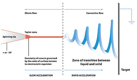
When a sufficiently high voltage is applied to a liquid droplet, the body of the liquid becomes charged, and electrostatic repulsion counteracts the surafce tension and the droplet is stretched; at a critical point a stream of liquid erupts from the surface. This point of eruption is known as the Taylor cone. If the molecular cohesion of the liquid is sufficiently high, stream breakup does not occur (if it does, droplets are electrosprayed) and a charged liquid jet is formed.
As the jet dries in flight, the mode of current flow changes from ohmic to convective as the charge migrates to the surface of the fiber. The jet is then elongated by a whipping process caused by electrostatic repulsion initiated at small bends in the fiber, until it is finally deposited on the grounded collector.[4] The elongation and thinning of the fiber resulting from this bending instability leads to the formation of uniform fibers with nanometer-scale diameters.[5]

Diagram showing fibre formation by electrospinning
Parameters for electrospinning process:
- Molecular weight, molecular-weight distribution and architecture (branched, linear etc.) of the polymer
- Solution properties (viscosity, conductivity and surface tension)
- Electric potential, flow rate and concentration
- Distance between the capillary and collection screen
- Environmental parameters (temperature, humidity and air velocity in the chamber)
- Motion and size of target screen (collector)
- Needle gauge
Modification of the spinneret and/or the type of solution can allow for the creation of fibers with unique structures and properties. Electrospun fibers can adopt a porous or core–shell morphology depending on the type of materials being spun as well as the evaporation rates and miscibility for the solvents involved. For techniques which involve multiple spinning fluids, the general criteria for the creation of fibers depends upon the spinnability of the outer solution.[5] This opens up the possibility of creating composite fibers which can function as drug delivery systems or possess the ability to self-heal upon failure.[26][27]
Co-axial electrospinning
A coaxial setup uses a dual-solution feed system which allows for the injection of one solution into another at the tip of the spinnerets. The sheath fluid is believed to act as a carrier which draws in the inner fluid at the Taylor Cone of the electrospinning jet.[5] If the solutions are immiscible then a core shell structure is usually observed. Miscible solutions however can result in porosity or a fiber with distinct phases due to phase separation during solidification of the fiber. For more advanced setups, a triaxial or quadaxial (tetra-axial) spinneret can be used with multiple solutions.
Emulsion electrospinning
Emulsions can be used to create core shell or composite fibers without modification of the spinneret. However, these fibers are typically more difficult to produce compared to coaxial spinning due to the greater number of variables which must be accounted for in creating the emulsion. A water phase and an immiscible solvent phase are mixed in the presence of an emulsifying agent to form the emulsion. Any agent which stabilizes the interface between the immiscible phases can be used. Surfactants such as sodium dodecyl sulfate, Triton and nanoparticles have been used successfully. During the electrospinning process the emulsion droplets within the fluid are stretched and gradually confined leading to their coalescence. If the volume fraction of inner fluid is sufficiently high, a continuous inner core can be formed.[29]
Electrospinning of blends is a variation of this technique which uses the fact that polymers are generally immiscible with each and can phase segregate without the use of surfactants. This method can be simplified further if a solvent which dissolves both polymers is used.[30]
Melt electrospinning
Electrospinning of polymer melts eliminates the need for volatile solvents in solution electrospinning.[31] Semi crystalline polymer fibers such as PE, PET and PP, which would otherwise be impossible or very difficult to create using solution spinning, can be created. The setup is very similar to that employed in conventional electrospinning and includes the use of a syringe or spinneret, a high voltage supply and the collector. The polymer melt is usually produced by heating from either resistance heating, circulating fluids, air heating or lasers.[32]
Due to the high viscosity of polymer melts, the fiber diameters are usually slightly larger than those obtained from solution electrospinning. The fiber uniformity upon achieving stable flow rates and thermal equilibrium, tends to be very good. The whipping instability which is the predominant stage in which the fiber is stretched for spinning from solutions can be absent from the process due to the low melt conductivity and high viscosity of the melt. The most significant factors which affect the fiber size tend to be the feed rate, the molecular weight of the polymer and the diameter of the spinneret. Fiber sizes ranging from ~250 nm to several hundreds of micrometershave been created thus far with the lower sizes being achieved using low molecular weight polymers.[33]
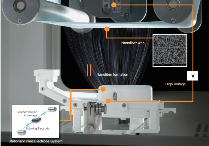
Examples: Electrospinning process of “NanospiderTM” equipment

Source: Elmarco-Asia_Company-Brochure_202005.pdf (kazelfacorp.com)
Example of Good practice:
Electrospinning of continuous nanofiber hollow yarns for thermal storage and insulation by a multi-step twisting method
(sagepub.com/journals-permissions, Textile Research Journal 2020, Vol. 90(9–10) 1045–1056DOI: 10.1177/0040517519886023)
- phase change nanofiber hollow yarns were designed.
- the hollow yarn structure is proposed to provide insulation for fabrics, while the phase change material is added due to its capacity to store thermal energy
- the ultrafine fibers for yarn fabrication are about 100–400 nm in diameter.
- due to the coupling of air for thermal insulation and PCMs for thermal regulation, the prepared hollow yarns and their fabric products have a better buffering effect against external thermal radiation and may have prospects in intelligent protective clothing.


Fig. Cross-sectional appearance of the hollow yarns: multi-layered hollow structure (a) with
residual polyvinyl alcohol (PVA) tube closely adhered, (b) with PVA extracted clean and (c) with
irregular PVA skeleton attached
Fig. The semi-automatic loom
