1. Pullover with Raglan sleeves, collar and neck gore
1. Description of the knitwear
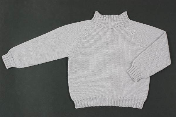
Single jersey, Starting stitch 2x2, E 7.2
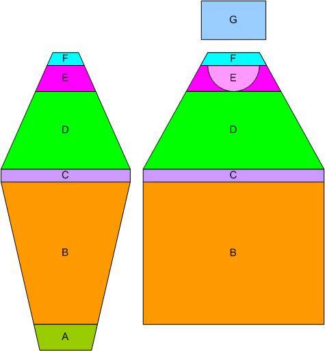
The areas marked in the figure are:
- A - sleeve/body length difference even-numbered, starting with 30% difference Short body or Short sleeve is valid;
- B – the length before connection as desired;
- C - sleeve body connection (6 rows) no widening or narrowing allowed;
- D - length after connection;
- E - neck gore even-numbered;
- F - gore distance until the end line as desired;
- G - collar height as desired.
STEP 1: CREATING SHAPE
In Function the desired attribute to the Narrowing edge is made (Shape element Neck gore in the front);
Creating
a new element ![]() type Gore;
type Gore;
Specifying the coordinates for the Neck gore via Line Editor (Option Line editor: the gore steps can be repeated via the factor);
Specifying the Neck gore distance until the end line

7) Creating Back detail
Allocating the desired attributes Widening and Narrowing to the edges under Function.
8) Creating Collar
Allocate the Binding-off tab to the end line under Function.
Select the Neck or the Fast cut-out binding-off module.
All shapes and k&w file have to be saved in the same directory. The shape size of the front and the back must be identical.
STEP 2: LOADING AND ADJUSTING SHAPES IN SHAPEWIZARD
Starting ShapeWizard;
Uploading the shape parts;
Specifying the 2x2 Collar knitting mode front/back via ![]() selection menu;
selection menu;
2) Settings in the ShapeWizard
The docking points are calculated and the k&w arrangements are loaded.

STEP 3: SETTING THE DOCKING POINTS
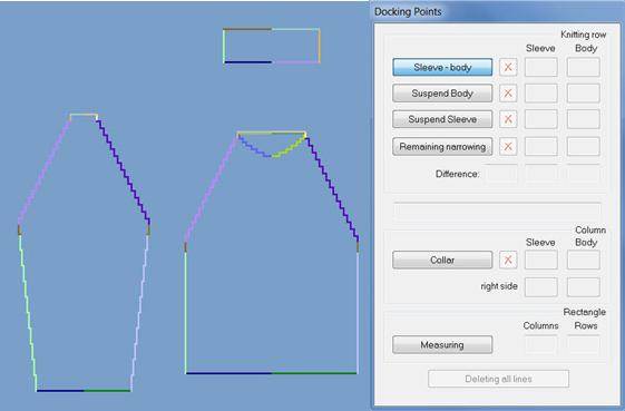
2) Setting the docking points;
Selecting a docking point;
Holding down the LMB on the edge of the shape part;
Moving the cursor to the edge of the connecting shape part and specifying the end position of the connection by releasing the LMB;
For removing an existing connection a Delete button is used. Via + and – keys from the keypad the shape view could be zoomed in or zoomed out.
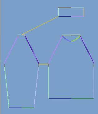
3) Needed docking points;
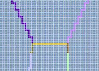
- Sleeve-Body
The sleeve body connection determines the position of all Areas to each other. The knitting sequence for the sleeve-body connection is entered until the connection line.
- Collar
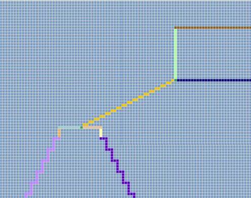
After folding-in the sleeve the collar will lie against the outer edge of the sleeve.
STEP 4: GENERATE K&W FILE
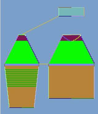
Activating Determine k&w arrangements
Saving the k&w file
Closing the ShapeWizard
2) Initialize
The determined k&w arrangements are deleted and the shape parts are reloaded. When changing the settings or correcting the shape, the k&w file must be newly determined.
STEP 5: CREATING BASIC K&W PATTERN
1) Selecting New File
2) Entering the name of the pattern
3) Selecting the machine
4) Selecting k&w pattern
5) Entering the height and width of the pattern field (With k&w the size of the pattern field is automatically doubled in height and width)
6) Select the knitting mode Jersey for the basic pattern via the selection list

STEP 6: OPENING AND POSITIONING SHAPE
1) Activating Position Shape
2) Loading the k&w file via
The k&w file is loaded centered in the basic pattern. The left sleeve is folded-in so that the L0 layer lies on the L1 layer. The right sleeve is automatically mirrored.
3) Positioning and presentation
Positioning of the shape parts after opening the basic pattern is possible. The pattern presentation can be changed according to the requirements. For inserting the Color and Module Arrangements. For row-accurate design of structures and motives within the shape.

STEP 7: CUTTING
1) Activating Cut-out shape
2) With the settings could be selected the k&w start.
The start module and the information of the k&w Arrangements will be applied to the pattern.
3) Activating the Yarn field dialog box
Automatic allocation of the Knot modules in standard situations.
Automatic allocation of the Knitting-in and out modules in standard situations.
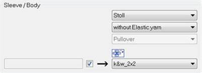
Pattern related settings in the Configuration k&w dialog box could be made before and after cutting out.
STEP 8: EXPANDING AND COMPLETING
1) Activating Processing step Complete expanding
2) Carrying out the desired setting of the widening correction and confirm it
3) Activating Processing step Technical processing
4) Generating MC program
5) Starting Sintral Check
